A single pressure-drop number rarely explains why a flow path underperforms. A sharp turn, sudden expansion or poorly placed inlet can redistribute momentum and create recirculation. The engineering question connects those local effects to the equipment’s overall duty.
Simple to use · Autonomous engineering engine
Your problem. One connected workflow.
Bring the drawing and the flow question. SIA handles the modelling workflow—from interpreting the fluid domain to mesh, solver and result checks—so you can focus on the geometry change that matters.
Start in plain language. Add the drawings or data you have. SIA handles model selection and tool orchestration, asking for the physical inputs that materially affect the answer.
From your question to the decision
Turn the drawing into a fluid domain
Identify the actual passages, inlet and outlet sections, scale and flow direction. Resolve consequential ambiguity before constructing the geometry.
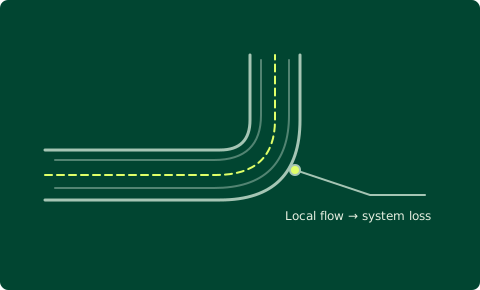
Connect local flow to overall loss
Inspect velocity, pressure and recirculation in the bend or transition. Keep static-pressure change distinct from irreversible total-pressure loss, especially where section area changes.
Test the design hypothesis
Compare a smoother transition, different radius or altered inlet arrangement at the same operating basis. Check both the integrated loss and the local region that motivated the redesign.
What changes the decision
A useful flow model explains where to intervene, not just how colourful the flow field looks.